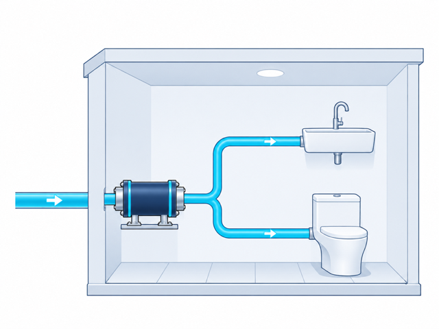
Localized scope
One room or fixture group
Install on the branch serving a defined restroom, laundry area, treatment room, or specialty cleaning zone.
The installation point determines the scope—from a single room or operational zone to a broader plumbing branch or building main.
Install on the branch serving a defined restroom, laundry area, treatment room, or specialty cleaning zone.
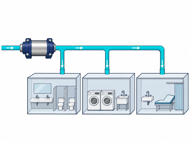
Treat the water distributed to a department, floor, restroom bank, or operational area from one accessible line.
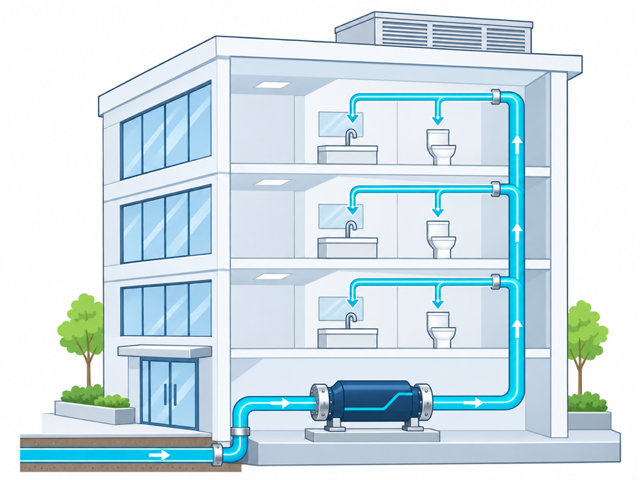
Position at the appropriate building entry point so downstream outlets receive water that has passed through BeLife.
The JR East study describes water accelerating through the internal core and entering a rotating flow. The pressure decrease releases dissolved gas and creates microbubbles and ultrafine bubbles in the water.
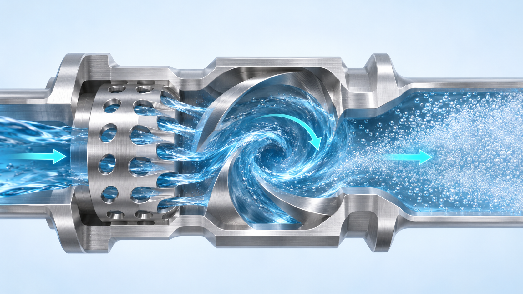
Water passes through openings in the internal core.
The geometry creates rotating flow and a low-pressure region.
Dissolved gas forms microbubbles and ultrafine bubbles in the downstream water.
Water conditions and existing treatment equipment are evaluated alongside the plumbing—not after installation.
Confirm access, nominal size, pressure, flow, available space, downstream scope, and the complete treatment train.
Record the water source, temperature, pH, conductivity or TDS, and the dissolved-gas or oxygen measure specified by Fuji Keiki.
Select the pilot scope and verify compatibility with filters, softeners, reverse osmosis, UV, aeration, pressure tanks, and well-water equipment.
A qualified plumbing professional installs the selected unit, and the site follows the agreed operating and observation plan.
Record baseline water conditions, operating settings, limitations, maintenance context, and defined pilot outcomes.